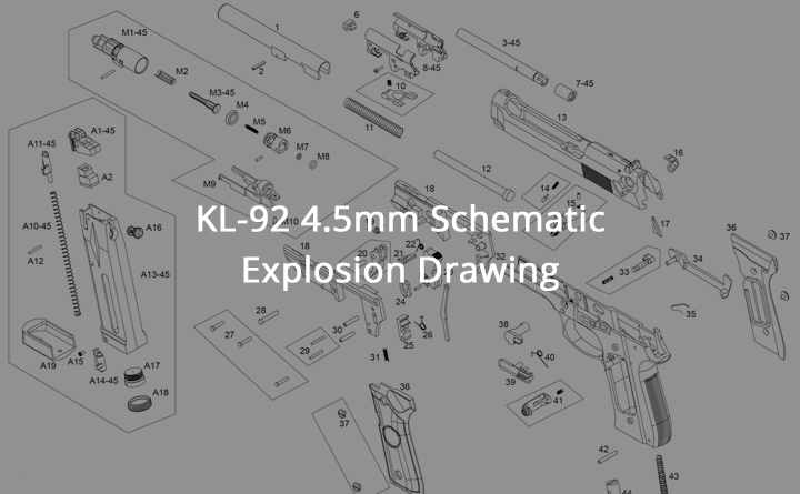
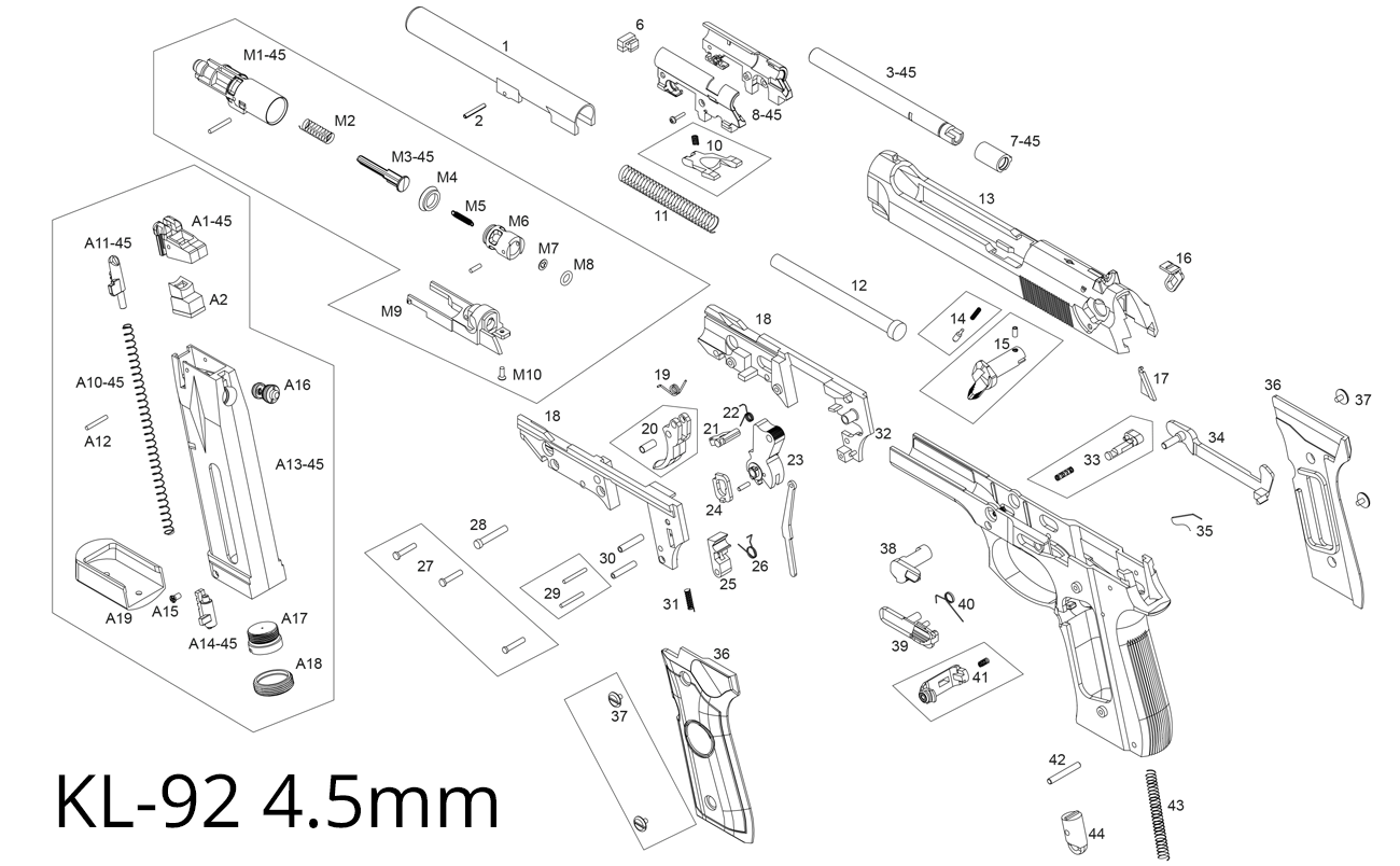
EXPLOSION DRAWING
This is the KL-92 4.5 MM Schematic Co2 Ver Explosion Drawing. Use this diagram and chart to find the Airgun part you need. This information is for all Krown Land 92 4.5 Air Pistols found on the Just Air Guns website within the Air Pistols section.
| A1-45 | MAGAZINE LIP |
| A2 | AIR NOZZLE RUBBER |
| A9 / A12 | PIN |
| A10-45 | MAGAZINE SPRING |
| A11-45 | MAGAZINE BAR |
| A13-45 | CO2MAGAZINE FRAME |
| A14-45 | MAGAZINE FRAME STOPPER |
| A15 | SCREW |
| A16 | CO2 MAGAZINE VALVE |
| A17 | CARTRIDGE STAB |
| A18 | CARTRIDGE BASE COVER |
| A19 | MAGAZINE BOTTOM |
| M1-45 | AIR NOZZLE |
| M2 | AIR VALVE SPRING |
| M3-45 | AIR VALVE |
| M4 | PISTON RING |
| M5 | AIR NOZZLE SPRING |
| M6 | PISTON |
| M7-M8 | CS / O RING |
| M9 | CYLINDER BASE |
| M10 | SCREW |
| 1 | OUER BARREL |
| 2 | BARREL PIN |
| 3-45 | INNER BARREL |
| 6 | CUSHION |
| 7-45 | HOP UP BUCKING |
| 8-45 | HOP UP CHAMBER |
| 10 | BARREL LOCK |
| 11 | RECOIL SPRING |
| 12 | RECOIL SPRING GUIDE |
| 13 | SLIDE |
| 14 | SAFETY - LEVER LOCK |
| 15 | SAFETY LEVER L |
| 16 | SAFTEY LEVER R |
| 17 | SAFETY LEVER BAR |
| 18 | TRIGGER BASE |
| 19 | TRIGGER SPRING |
| 20 | TRIGGER |
| 21 | HAMMER LEVER |
| 22 | HAMMER LEVER SPRING |
| 23 | HAMMER |
| 24 | STOP PLATE |
| 25 | SHEAR |
| 26 | SHEAR SPRING |
| 27 | SCREW |
| 28 | TRIGGER PIN |
| 29 | PIN |
| 30 | BRASS TUBE |
| 31 | STOP PLATE SPRING |
| 32 | FRAME |
| 33 | SLIDE RELEASE BUTTON |
| 34 | TRIGGER |
| 35 | TRIGGER LINK |
| 36 | GRIP |
| 37 | GRIP SCREW |
| 38 | SLIDE RELEASE LEVER |
| 39 | SLIDE STOP |
| 40 | SLIDE STOP SPRING |
| 41 | MAGAZINE RELEASE BUTTON |
| 42 | PIN |
| 43 | HAMMER SPRING |
| 44 | HAMMER SPRING COVER |
KL-92 4.5MM SCHEMATIC CO2 VER EXPLOSION DRAWING
This is the Explosion Drawing for the KL-92 4.5mm Schematic Co2 Ver.
The KL-92 4.5mm CO2 Schematic, often called an “explosion drawing,” is a detailed visual representation that dissects the air pistol into its fundamental parts, showcasing how each component fits the overall design.
It is presented in an exploded format, where individual parts, such as the slide, barrel, trigger assembly, CO2 cartridge chamber, magazine, and internal springs, are separated but aligned to illustrate their precise arrangement within the airgun.
Each part is labelled with a reference number and name, providing a clear view of the internal mechanism, including the firing pin, hammer, safety, and magazine release components. This layout helps users understand the assembly and disassembly process, making it ideal for troubleshooting, maintenance, and customization.
If you need to replace or upgrade parts of your air gun, find the part in the diagram. Then, in the list of parts below, click on the part name to ensure the part number is correct.
If you have any questions about this page, please use the contact information on this website to contact our support team.